The Lever Link
© Jeff Roberson
Created: 2008-Apr-24
Edited: 2009-Dec-22
Revision History
Abstract
About 30 years ago, designers provided a full-span aerodynamic roll control surface for flex wing hang gliders when they cut the fixed connection between the keel and the crossbar (i.e. The Floating Keel or Floating Crossbar). By allowing the keel to float relative to the crossbar/leading edge structure, true wing warping roll control became possible. However, strong sail tension has for decades hidden the true potential of this aerodynamic roll control surface because the sideways force of the pilot on the keel is relatively weak. The Lever Link hang system described in this article provides the missing piece to this puzzle: a control linkage which connects the full pilot's weight directly to the full-span wing warping control surface in a levered manner to easily overcome the inherent stiffness due to large sail tension. This device should provide significantly improved roll control authority to flex wing hang gliders, resulting in improved safety, performance and ease of flight.

Forward
I am a small guy (I weighed under 130 lbs for many years - but have since grown into a fat bastard). But I do like to fly larger gliders because: 1.) they get a better sink rate, 2.) they turn tighter, 3.) they land slower and 4.) the best gliders from the manufacturers always seem to come in the larger sizes (large for my size, that is). Now I have long arms and pretty good upper body strength and can handle the bigger sizes, but I'm frequently frustrated by the lack of control authority in the roll axis and the amount of "muscling around" required to get the glider pointed in the right direction. Sometimes when flying in big air (which we get a lot of here in Utah), I'll shift my weight ALL THE WAY OVER to one side, but nothing happens for quite some time - it feels as though I am placing an order for a turn! This is very disconcerting (and downright dangerous) when one wing gets popped up coming in on final approach into a restricted LZ! Trained as an Engineer (B.S. Civil and Environmental 1981) and motivated as a turn-challenged, light weight pilot, I took a hard look at this whole roll control problem some time ago (in 1984 - and have been contemplating it ever since). I did come up with a really good idea that was so simple, I was surprised that it had not been incorporated yet. Over the years, I have waited for the manufacturers to provide a manifestation of this simple device, but alas, it has yet to surface. I have tried to explain this idea to quite a few people (some notable), but no one has really taken notice. I guess its just hard to explain this in words - it really needs to be shown with moving pictures and free-body diagrams which graphically demonstrate the beneficial effects. Thus, motivated by a thread on the Oz Report Forum, I have decided to run this idea up the flagpole and see who salutes. So ladies and gentlemen, please allow me to introduce... The Lever Link!
Note: If you are interested in this lever link idea and would like to discuss it further, please post any thoughts, criticisms, and/or questions to the following forum threads: "Power Steering" at OzReport.com and/or "Any Engineers in here? (need feedback on Lever Link idea)" at Hanggliding.org.
Introduction
A hang glider is a delta shaped flying wing that is controlled primarily via weight shift by the pilot who is suspended some distance below the wing. Lets look at the three axis of control. In pitch, the pilot has superb control authority and can quickly adjust the angle of attack with minimal effort. No problem here. In yaw, the delta shape of the wing has a significant sweep angle which provides a very strong aerodynamic stabilizing force. Thus, in yaw, a hang glider is inherently stable and requires no control input from the pilot. No problem here either. Now roll control is another story and is the subject of and reason for this article. It is this author's opinion that roll control authority in high performance hang gliders is weak at best and can be dangerously lacking at worst. However, roll control authority for a hang glider can be significantly improved by implementing a simple mechanism which, using the age old principle of mechanical leverage, amplifies the sideways roll force that the pilot provides when he/she shifts to one side. This is achieved by providing a simple control linkage which directly connects the weight of a hanging pilot to the built-in floating keel wing warping aerodynamic roll control surface. I call this device the Lever Link which is the subject of this article.
Assumptions and Glider Configuration
For the purpose of this article we make some assumptions and have simplified the glider design as follows:
- We consider only the forces in the "rolling" plane perpendicular to the longitudinal axis. We do not address forces in other planes (i.e. drag and the forward component of lift which balances out the drag.)
- The glider is flying in a steady-state straight line path with wings level and is descending at a constant sink rate. Roll forces are applied instantaneously and we look at the effect of these forces before any rolling actually occurs.
- The center of gravity is located at the center of the pilot (i.e. the glider is weightless).
- All members making up the hang glider structure are perfectly rigid. There is no bending, stretching, twisting or compressing of any individual members.
- The sail is free to change shape as the keel moves relative to the crossbar (i.e. billow shift).
- The crossbar is a single straight member connected at each leading edge junction. The crossbar is not connected to the keel - (except for the glider in Figure 1 which has its crossbar bolted to the keel).
- The crossbar passes over the keel at a point just above the hangstrap location.
- There is no VG system and no crossbar tension haul-back mechanism.
- There is no kingpost or upper rigging.
- The sail keel pocket has zero height and no "play". i.e. the left and right sails are connected directly to the keel. Billow shift occurs only when the keel moves.
On the mechanics of Hang Glider roll control
To understand how and why the Lever Link works, one needs to first grasp the mechanics of how a hang glider rolls. There are two main force vectors that play together to make this happen; 1.) The force of gravity (Fg) which acts on the center of gravity (CG) (located near the center of the pilot), and 2.) the aerodynamic force of the air (Fa) which acts on the center of pressure (CP) (located near the center of the sail). (See Figure 1.)

Figure 1. External forces acting on a glider in flight (view from the rear looking forward)
Now both of these forces are vectors which are mathematical constructs having both a magnitude and a direction. The direction of the force of gravity (Fg) is always directed straight down towards the center of mass of the earth and the magnitude is the weight of the pilot (we will ignore the weight of the glider for this discussion). The direction of the aerodynamic force (Fa) is straight up when flying in a straight line at constant speed (actually the lifting force of the wing has a forward component which counteracts the drag force, but that acts in another plane and does not affect roll so we will ignore that too). The CP is typically located near the center of area of the sail as viewed from the top, but this position varies as the shape of the sail and angle of attack changes. In steady state straight line flight, Fg and Fa have equal magnitudes and are co-linear (on the same vertical line) and no rolling force exists. To roll, there must be a rotational force, or Moment, which tends to rotate the glider about its longitudinal axis (this longitudinal axis is perpendicular to the plane shown in Figure 1 and is parallel to the flight path).
Note: The force of gravity actually acts on each and every particle of mass of the aircraft (glider and pilot). But by using the principle of equivalent forces, we can replace the sum of all these individual particle forces with one equivalent Resultant force which acts at the center of mass (or center of gravity). Similarly, the aerodynamic force of the air is actually a distribution of pressure acting on every square inch of the sail area. This distributed pressure of the air on the entire sail can also be replaced by a single resultant force which acts at the center of pressure (or center of lift).
On Forces and Moments
In Physics and Engineering there are two entities which can be applied to a rigid body to cause motion: 1.) a Force which tends to cause a Translational motion (if the force's line of action passes through the body's center of gravity), and a Moment (or torque) which tends to cause a Rotational motion. A rigid body in space always rotates about its center of gravity. A pure moment (or force couple) is achieved by applying two parallel forces having equal magnitude but opposite directions which act some distance apart. (Note that we use the term "moment" and not "torque" in this discussion.) A single force also tends to cause a rotation if its line of action does not pass through the center of gravity. The magnitude of a moment of a force about any point on a rigid body is equal to the force times the perpendicular distance (or moment arm) from the force. e.g. When you push down on the pedal of a bicycle you are creating a moment about the axis of the crank. In the figure above, the pilot having a weight equal to Fg has shifted her weight to the left by a distance d which has resulted in a pure counter-clockwise rolling moment which is equal to F times d. (i.e. If the pilot weighs 120 pounds (lbs) and moves 1.5 feet (ft) to the left, the rolling moment is 120 * 1.5 = 180 ft-lbs).
Roll moment due to pilot CG shift (i.e. Weight Shift)
When the glider airframe is a static rigid structure (i.e. the crossbar is bolted to the keel), the keel cannot move relative to the crossbar, so the sail cannot shift (i.e. no billow shift will occur with our keelpocketless design). This situation is illustrated in Figure 1 above. When the pilot shifts her weight, then the resulting rolling moment is due to the displacement of the CG only - the CP does not move.
The keel really wants to float!
But modern gliders do have a floating crossbar (or floating keel) design, which allows the keel to move relative to the crossbar. For this discussion, our simplified "floating crossbar/keel" hang glider can be thought of as a machine (having moving parts) composed of two static rigid structures which move relative to each other. The first (upper) structure consists of the two leading edges and crossbar. The second (lower) structure consists of the control bar, keel and front/rear wires. The lower structure is attached to the upper structure as follows; the front of the keel is attached to the nose plate with a pin joint and the rear of the keel is attached to the outboard leading edges by the sail which can be considered to be a "spring-like" member (whose K factor varies with VG setting). The lower portion of the control bar is attached via the side wires to the upper structure leading edge/crossbar junctions.
With this configuration, the lower keel/control bar structure hangs from the upper structure from three points only (noseplate and L & R leading edges). If you remove the sail from the picture, the tail of the keel is completely free to wag (float) back and forth relative to the upper structure pivoting about the noseplate. The side wires DO NOT impede the motion of the apex of the control bar. In fact, if you look at the plane which contains the control bar and the side wires (where most of the forces are going), it has the same geometry as a pitchy, which (like the original French Connection device invented by Darlet), is a device which provides an elevated virtual hang point. This geometry with its shallower effective circular arc significantly reduces the force required to achieve a displacement and allows the keel to wag with ease (see Figure 2.)

Figure 2. Uninhibited "Pitchy" keel motion (animation)
Note that (when unimpeded as shown) this pitchy geometry places the effective hang point way above the glider (and above the animation image) providing a long arm for the pendulum side to side motion. Note also that as the pilot shifts left, both the pilot and the apex of the control bar move ever-so-slightly up in a gentle circular arc (shown in blue). This gentle arc provides a small stabilizing force which tends to restore the keel back to the center position.
Summary: The geometry of a floating keel hang glider is such that the keel is unimpeded and free to move from side to side. Thus, any sideways force applied to the keel will tend to move it.
Roll moment due to sail CP shift (i.e. Wing Warping)
As mentioned in the introduction, a hang glider is primarily controlled using weight shift. Actually, there is a moving aerodynamic control surface at work here too: The wing itself. When the keel is moved to the left, the center of the sail moves with it which pulls more billow into the left wing (loosening it) and less into the right wing (tightening it). (See Figure 3.)

Figure 3. Lifting Forces and Wing Warping CP Shift (animation)
In the upper wing in the figure, we have divided the total aerodynamic lifting force into two components: the left wing and the right wing. When the keel is displaced to the left, the lift increases on the right wing because it is tighter which increases its effective overall angle of attack. The opposite occurs on the left wing where lift is reduced. The net effect is illustrated in the lower wing of the figure. The center of pressure moves significantly when we apply this wing warping keel displacement. Yes, a flex wing hang glider most definitely has an active aerodynamic roll control surface (wingerons? warperons?). When a pilot shifts her weight to the left, this applies a leftward force on the keel which tends to cause the effect illustrated above.
Note: In this article we refer to "billow-shift" as the difference between the right and left sail trailing edge curve as viewed from the rear and we illustrate this as a circular arc. In actuality, with a modern tight sail bladewing, the trailing edges are quite flat and this "billow shift" will manifest primarily as differential tip washout. The resulting effect is the same - differential lift between the left and right wings which results in a tendency to roll the glider.
Summary of flex wing roll mechanics
Thus, a glider rolls to the left due to a rolling moment M caused by a force couple consisting of the force of gravity (Fg) acting at the center of gravity (CG) and the aerodynamic force (Fa) acting at the center of pressure (CP), separated by a moment arm distance d. This moment arm distance d is a combination of two components; 1.) the leftward displacement of the CG (caused by the shifting pilot) and 2.) the rightward displacement of the CP (caused by the warping of the wing shape due to horizontal keel displacement).
Sail Tension and Wing Warping
So when a pilot pushes her body to the left with a force of 40 lb, that 40 lbs of sideways force is transmitted to the keel and most of this sideways force is passed directly to the keel pocket of the sail. But is 40 lbs of sideways force enough to elicit a significant wing warping effect? Lets look at the sail tension forces at the keel pocket and see if we can shed some light on this question. Now the weight of the pilot bears down on the keel at the hang point and this vertical load is mostly taken by the control bar but some of it is taken by the center of the sail at the keel pocket. As a rough-ass-guess (RAG), lets assume that the control bar supports 3/4 (75%) of the vertical load and the center of the sail supports 1/4 (25%). The sail attachment to the keel is at a low angle from each side - the billow angle. Lets call this α (the lower case Greek ALPHA character). Lets come up with an equation that determines the sail tension T given the billow angle α and the vertical keel load supported by the sail (Fkv). (See Figure 4.)

Figure 4. Sail Tension Vertical Loading
Using this equation, lets compute a table of sail tensions for a variety of billow angles. Lets assume a pilot weight of 200 lbs, and the (RAG) portion of this supported by the sail (25%) is 200 * 0.25 = 50 lbs. The following table shows the sail tensions required to support 50 lbs of vertical load:
| Billow Angle - α (degrees) | Sail Tension (lbs) |
|---|---|
| 0.5 | 2865 |
| 1 | 1432 |
| 2 | 716 |
| 3 | 478 |
| 4 | 358 |
| 5 | 287 |
| 6 | 239 |
| 7 | 205 |
| 8 | 180 |
| 9 | 160 |
| 10 | 144 |
| 11 | 131 |
| 12 | 120 |
| 13 | 111 |
| 14 | 103 |
| 15 | 97 |
(Disclaimer: The 25%/75% load distribution ratio is a rough guess. Real sail tensions might be significantly different from these values.) But if this guess is close to the mark, you can see that sail tension at lower billow angles is significant, on the order of hundreds of lbs. Thus when a pilot shifts their body to the left with 40 lbs of force, this represents a small fraction of the sail tension, and thus, very little billow shift occurs. But this is what we already know from years of flying bladewings on tight VG. So even though "the keel really wants to float", with a tight sail and relatively low sideways forces, the floating keel does not really "float" very much at all. To turn, we rely primarily on the rolling moment component due to the pilot CG weight shift, (and the rolling moment due to wing warping CP shift plays a distant second fiddle). In summary: high sail tension inhibits wing warping.
The Lever Link
The main thing limiting free keel wing warping motion in real flight is the (significant) sail tension, which is strong relative to the meager side forces imparted by the pilot's hang strap when weight shifting. When the VG is loose (e.g. a Falcon), there is plenty of billow "play" in the sail and the keel moves easily and roll control is adequate. But on a bladewing with tight VG, the sail holds the keel in place quite effectively (which explains why they are "stiff"). The Lever Link idea described here can dramatically improve this situation, but to explain how it works, we need to first review the lever principle.
The Lever Principle
Lets illustrate this with an engineering statics problem. (Yes there is a little math but its pretty basic.) Here's the problem: You need to push a large nail in the wall near the ceiling but you can't bang it in with a hammer (because it is 2am and the neighbors are sleeping - you must push it in silently). (See Figure 5.) The nail requires 200 lbs of force to go in but you can only push with 50 lbs of force with your hands. Now you also have a 50 cm pry-bar at your disposal and there is a conveniently placed pipe 10 cm above the nail location that you can use to lever against (Note that this family is trying (without total success) to go metric ;^). You place one end of the pry-bar under the pipe and position it also over the nail. With 50 lbs of force, how far down the pry-bar (distance "d") must you push to get the nail to go in? (And for extra credit, how hard must you push if you push against the end of the pry-bar?)

Figure 5. The (contrived) nail-in-the-wall lever illustration problem.
To solve this, we bring out the Engineer's secret weapon: the Free Body Diagram. With this tool we look at only one part at a time (in this case the pry-bar only). When a part is isolated like this, all its connections to the outside world are replaced by equivalent external forces (in this case the forces of your hand, the nail and the pipe). Now for this problem we have two equations at hand: 1.) the sum of all forces in the x direction must be zero, and 2.) the sum of all moments about the z axis (perpendicular to the page) at any point (in this case point A located at the nail) must be zero. We use the first equation to find the force of the pipe (Fp) and this makes perfect sense. We need 200 lbs and we are pushing with 50 lbs so the pipe must make up the difference: 200 - 50 = 150 lbs. To find the distance d we look at the sum of the moments about point A located at the nail. We note that the 150 lb pipe force (Fp) acting with a moment arm of 10 cm must be equal and opposite to our 50 lb hand force acting with a moment arm of d cm. A little bit of basic algebra yields a distance of 30 cm. Thus, we have shown how a simple lever can easily result in a fourfold increase in force (from 50 to 200). Easy-peasy!
Forces on the keel
Lets first take a look at the forces of the pilot that are transmitted to the keel via the hangstrap. To initiate a left-hand turn, a 200 lb pilot pushes his body over to the left with a force of 40 lbs (20 lbs per hand). This situation is illustrated in Figure 6 which also shows a free-body-diagram of the hangstrap. Looking from the rear the angle of the hangstrap of the displaced pilot is 11.31° degrees.

Figure 6. Forces on the keel
Now the apex of the control bar will support the vertical component of the hangstrap force (weight) and will freely move to the left and right as was shown in Figure 2. Some of the vertical load will be taken by the center of the sail attached to the keel but most of it is taken by the downtubes. But due to the pitchy geometry of the control bar and flying wires, nearly all of the side force applied to the keel from the hangstrap is taken by the center of the sail (and this force tends to directly cause wing warping which is what we want).
In this simple case, the sideways leftward force on the keel from the hangstrap is equal to the sideways force the pilot applies to the basetube (40 lbs). But there is another smaller sideways force placed on the keel that is to the right - opposite to what we want for a wing warping roll to the left. This force comes from the right rear wire, (which runs from the lower right control bar corner to the rear of the keel). When the pilot shifts her weight to the left, she pushes the basetube to the right with both hands, but she must also push forward with her right hand and pull backwards with her left to keep her body pointed straight ahead. If we look at a free-body-diagram of the forces acting on the pilot from a top-down-view, these (significant) pushing and pulling forces are required to counter-balance the moment caused by the sideways forces from the basetube to the hands and the sideways force from the hangstrap to the harness. (See Figure 6b.)

Figure 6b. Basetube Push/Pull Forces.
As the figure shows, if the hands are separated by 24 inches and the horizontal distance from the basetube to the harness main is 30 inches then the pushing and pulling forces must be 50 lbs each to achieve equilibrium. This push-pull force couple applied to the basetube (100 ft-lbs), results in tension forces in the right-rear and front-left wires. The force from the front left wire is applied to the noseplate and does not affect the keel wagging, but the right rear wire does apply a rightward force to the aft of the keel. A rough calculation of this side force is about 10 lbs. If the rear wires have a "pigtail" (where the two wires become one before attaching to the keel), then this side force is reduced. For the purpose of this discussion, we will ignore the side force from the rear wires.
Summary: All of the sideways force the pilot applies to the basetube (40 lbs) is transferred directly to the keel via the hangstrap, and most of this force is transferred to the keel pocket of the sail. But in the horizontal direction, the sail is tight and strongly resists moving horizontally. (Sounds like a job for our good friend the Lever!) Lets apply the same lever trick we used in the previous example to see if we can improve this situation.
Lever Link Design #1 ("The Pry-Bar")
Note: Please keep in mind that in the examples below, the diagrams show the forces applied to a theoretical glider having a very stiff sail (actually infinitely stiff because the keel does not move at all). This allows us to calculate and show the maximum sideways force that each Lever Link design can achieve. On a real glider the Lever Link will rotate and the keel and sail will shift long before the forces build up that far. Thus, the following diagrams illustrate the theoretical maximum sideways keel forces.
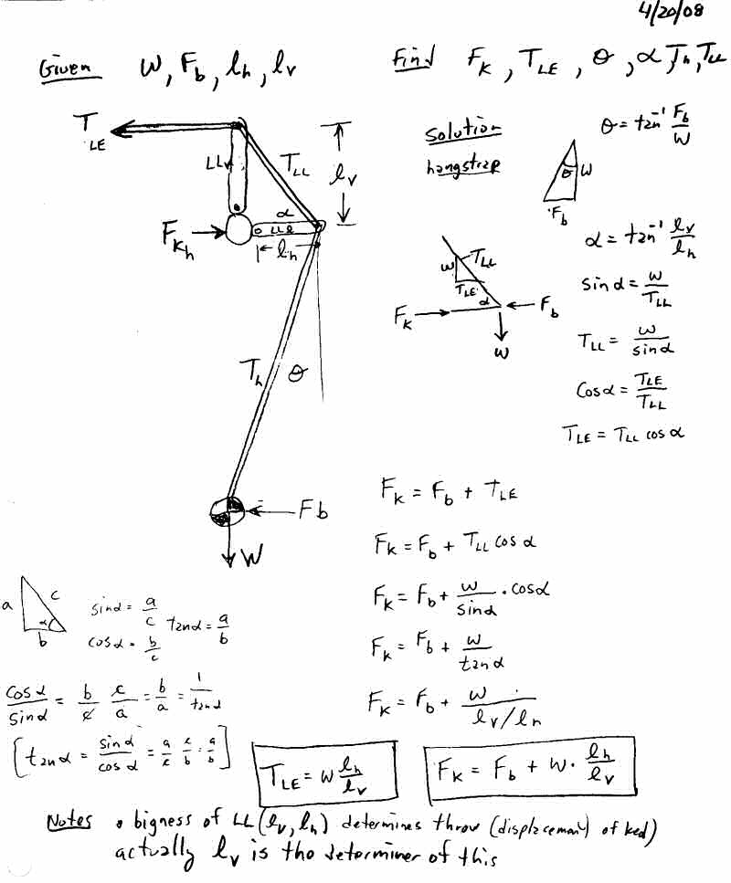
For our first iteration Lever Link lets build a simple vertical "pry-bar" that clamps to the keel but is free to rotate about it and is attached to the crossbar at the top and has holes at the bottom to which we can hook in. (See Figure 7.) The top length above the keel is 10 cm and the bottom hole length below the keel is 20 cm. The top connection has a vertical slot with a pin so that the crossbar can only take a sideways load (Fc). How much sideways force is applied to the keel (Fkh) when the pilot shifts over with 40 lbs of force?

Figure 7. Lever Link Iteration #1 "The Pry-Bar".
This first simple "pry-bar" Lever Link design amplifies the sideways force from 40 lbs to 120 lbs (a factor of 3). This design is only presented here because it clearly shows the lever principle in action - it has several major drawbacks preventing its use in the real world. Connecting the top of the linkage directly to the crossbar works only if the crossbar passes directly over the hang point - unlikely. Also the slotted pin link attach method is not very elegant. The bottom of the pry bar is a safety hazard ready to impale the pilot if things got upside-downy and the hang height is significantly reduced. And how it moves in the pitch direction would present problems. But you must admit that the 3X roll force amplification of this design is a pretty good improvement, but we can do better. Much better. In fact, in our next design, lets just get medieval on its ass!
Lever Link Design #2 ("The Bellcrank")
This next design illustrates the advantages for a much smaller and weaker pilot (lets say your kid sister), so we really need to crank up the roll force amplification. The pilot weight is a mere 100 lbs and the sideways force on the control bar is only 20 lbs (10 lbs for each hand). For this second iteration, lets use a bellcrank configuration (remember the control linkage from your old control line model airplanes when you were a kid?). This allows us to apply not just the sideways force from the hangstrap, but the full (levered) weight of the pilot to boot. In this design the bellcrank clamps to the keel and is free to rotate about it. (See Figure 8.) The top of the Lever Link is connected to the left and right leading edges (at the crossbar junction) with cables. The height of the vertical member is 5 cm and the width of the horizontal members is 10 cm. Two hang straps run down from the ends of the bellcrank all the way down to the pilot's harness, (which has been customized for this hang system).

Figure 8. Lever Link Iteration #2 "The Bellcrank".
Now with this design, we achieve an 11X keel force amplification from 20 lbs up to 220 lbs (more than one whole order of magnitude.) By flying with a Lever Link, this 100 lb featherweight pilot is applying more than 5 times the sideways force onto the keel as the 200 lb pilot flying without one (back in Figure 6), and she is pushing only half as hard. With this large horizontal force applied to the keel relative to the crossbar/LE structure, we can now effectively perform some real wing warping! Note that the increase in side force is equal to the pilot's weight times the ratio of the horizontal length divided by the vertical length. (See here for a derivation of the equation.) In this particular design the upper cables carry a load (Fc) equal to twice the full weight of the pilot (200 lbs) - these cables and the Lever Link itself must be built quite strong.
But this design also suffers some problems. The 11X amplification is likely significant overkill. (This exaggerated amplification example is only given to dramatically illustrate the power of the Lever Link principle - i.e. taking the pilot's weight and applying it in a levered manner sideways to the keel.) Although it provides lots of amplification, the 5 cm vertical member does not allow for much keel displacement - it is too short. And notice that with the two long hangstraps running all the way down to the harness that the pilot does not move very far before the 20 lbs of sideways force kicks in. In fact, the pilot is now somewhat "connected" to the motion of the keel, and the glider can actually move the pilot from side to side as it hits turbulence (i.e. tail wagging the dog), which would be undesirable. This design goes too far - the roll force amplification needs to be applied in a progressive manner, gradually increasing in proportion to the pilot's sideways displacement. Also, the single piece bellcrank will undergo some strong bending moments and would need to be built pretty hefty. A simple truss or a triangular plate design might be simpler and more robust. The next design addresses all of these problems.
Lever Link Design #3 ("The Truss")
For our third and final design, we build a practical experimental prototype Lever Link from standard tubing, cables, brackets and fittings in a space truss configuration (see Figures 9 and 10). We add several holes in the tubing so that we can easily adjust the geometry. The height of the vertical tube is chosen to just fit inside the double surface of the sail so that the whole mechanism is enclosed. We have two hangstraps with lengths similar to a standard glider but each strap connects to the carabiner independently. Thus, from the pilot's perspective, hooking in is the same as a regular glider and no harness mods are needed.

Figure 9. Lever Link Iteration #3 "The Truss".
Its not pretty, but this design would work for a designer to experiment with various amplifications and keel displacements. Note that with the shorter hang straps, the roll amplification progressively kicks in as the pilot moves to one side. When the pilot hangs in the center, there is equal force in each of the two hang straps, but as the pilot moves to the left away from the center position, the right hang strap takes more load and the left strap takes less. This continues until the pilot reaches the angle where the left strap goes slack and the right strap takes the full load. At this point, the maximum force amplification occurs. In our example here, the pilot has moved over at an angle of 11.31° degrees, a little less that half way to the maximum amplification angle. The sideways roll force achieved is 120 lbs which is a 3X amplification. Note that the effective hang point on the Lever Link is where the line of the harness main intersects the horizontal member as shown in the figure. (For a more rigorous (albeit sloppy) proof, see this page which solves for all the forces in the actual Lever Link members. It requires using two equations to solve for the two unknown tensions in the hangstraps.)
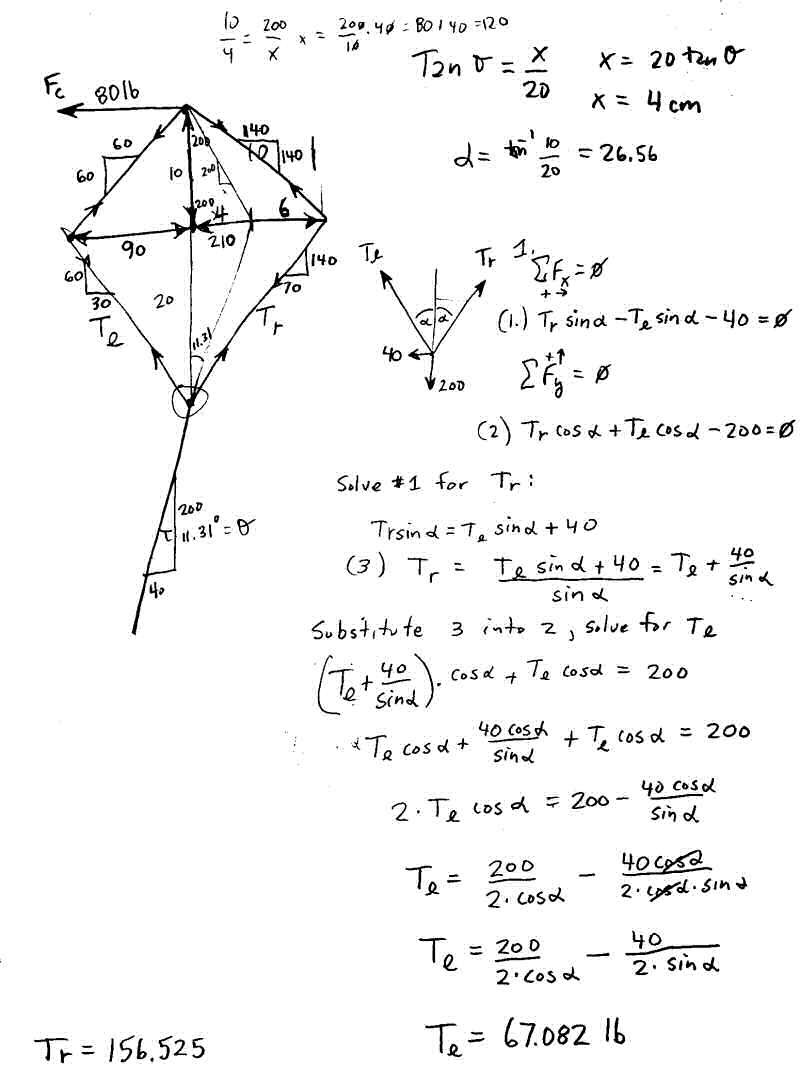
The Lever Link in 3d
Up until now we have looked at only the roll plane, but a real Lever Link must work in 3 dimensions. In particular, it must not only rotate about the keel when the pilot rolls, but it must also handle fore-aft forces when the pilot changes pitch. Thus, the Lever Link must have members that run forward and backwards. The scope of this article does not seek to complete the whole picture, but the following two figures show how a couple designs might look like in the real 3d world.

Figure 10. The "Truss" Lever Link in 3d. (Not pretty but it works.)

Figure 11. The "Plate" Lever Link in 3d.
Although these last two are workable designs (the "Plate" design is probably the most practical solution presented here), it is hoped that manufacturers will take this to a "whole 'nother level" and come up with an even better design which is lightweight, simple, reliable, robust, safe and effective and easy to set up. There are many solutions that could implement this Lever Link principle and this author hopes that the manufactures will take the ball and run with it. For my next glider, I want to move up from a 145 to 165 bladewing with a built-in Lever Link power steering device so that I can have an even better sink rate combined with real roll authority. I'm tired of placing orders for turns that never get filled!
Do we really need this device?
Well, no, we don't really need it - pilots have been flying hang gliders without this device since the beginning of time. But if you take a diverse group of hang glider pilots and ask them if they think roll control is A-ok as-is or could stand improvement, then separate them into two groups, you would have BIGGER and STRONGER folks over in one corner saying control is ok, and SMALLER and WEAKER folks in the other corner saying improvement would be welcome. Truth be told, we have been merely getting by (i.e. suffering) with lackluster roll control and have simply learned to make do with what we've been given. We have taken for granted that you must muscle a glider to make it turn and we have gotten used to it. Lets build a glider that incorporates a Lever Link hang system, try it out and see how it flys. My guess is that once we get a taste of true roll authority (i.e. power steering), there will be no going back. Wouldn't you like to be able to pull on full-race-mylar-in-your-face-VG and have roll response like a Falcon? Wouldn't you like a glider that is safer and less tiring to fly? And wouldn't it be nice for a 100 lb female to be able to roll a glider with the same authority as a 250 lb man? (And won't somebody please think of the children?! ;^) Dramatically improved roll response has absolutely no down side!
Thoughts
- Long time pilots are very accustomed to the way gliders currently fly. It may take some time to get used to flying a glider with much easier and pronounced roll control authority. Initially, over-controlling may be a problem.
- The Lever Link device design could incorporate an elevated hang point for reduced pitch pressure. Or better yet, design the glider with strong pitch stability (i.e. plenty of pitch pressure) but incorporate an in flight trim speed adjustment device. This could be built into the Lever Link to allow the pilot to set (and re-set) the fore-aft hang point position during flight. Set the trim fast for glides and slow for climbs! (Note that this is a separate idea that could be incorporated in other ways.)
- Some might argue that adding a Lever Link device to a flex wing glider is adding a new aerodynamic control surface which would require that a new class of glider be created. To this I say hogwash. As previously discussed, flex wing hang gliders have been equipped with this aerodynamic roll control surface since the invention of the floating crossbar (they flex right?). This device simply amplifies the effectiveness of the flex wing's built-in wing warping ability. No new class is warranted.
- With a Lever Link, gliders can be built much stiffer and still be controllable so the performance distinction between flex wings and rigid wings may become blurred.
- There may be a way to incorporate this lever principle by using a different shape/configuration of the control bar apex. The simple triangle (which has served us well) may not be the ideal solution.
Implementation Notes
- Needs to be safe. It must be very easy to set up and impossible to assemble incorrectly.
- Need a clever design that can easily fold up (or be removed) when glider is folded up.
- Sail, keel and crossbar will undergo much larger forces. They need to be built strong enough to handle the new increased loads.
- The sail keel pocket stitching will need to be built very beefy to withstand the large sideways keel forces.
- The glider will become more of a machine so the moving parts (e.g. keel-to-noseplate junction, the ends of the flying wires and the Lever Link mechanism) may need new bearings/bushings to allow for free motion and to reduce wear.
- It may be difficult to fit an appropriately sized lever arm inside the double surface (which is not terribly thick near the hang point).
- With power-steering-like roll authority provided by the Lever Link, wing design could be given some real dihedral to provide improved straight flight roll stability. We no longer need to "balance on the beach ball" (with anhedral) to get a glider with good thermalling characteristics.
- Designers will need to play around with the triangular geometry to balance out the roll magnification vs. the keel throw displacement for optimal handling. i.e. Advanced level gliders with tighter sails will need greater amplification and less keel displacements but intermediate and beginner level gliders with loose sails will need less amplification and more keel displacement.
Pros and Cons
Pros
- Power Steering!
- Makes stiff gliders soft.
- Allows small pilots to easily fly larger gliders.
- Allows large pilots to fly even larger and stiffer gliders.
- Safety. Better roll authority to correct for turbulence induced rolls near the ground (i.e. on launches and landings and everywhere else).
- Performance. Can roll more effectively into strong thermal cores.
- Efficiency. Improved roll authority makes flying physically less demanding. You can fly longer while doing less work. i.e. Flying is less tiring.
- Stability. Some dihedral could be added to the wing to provide much better straight line stability without compromising roll authority.
- Flexibility. Adjustable geometry and cable slackness allows for variable roll force amplification. The device could have a set of hang points, each one tuned for a different hook-in weight.
- Tuning. A turnbuckle arrangement in the Lever Link would provide a very simple and effective way to adjust out turns in glider.
- Pushes the edge. Allows building stiffer gliders that are now controllable.
- Performance. Allows aerobatic pilots a better tool for their trade. (Gliders may become much easier to spin - in addition to having enhanced ability to perform rolling maneuvers.)
- Simplicity. May eliminate the need for a VG system.
- Performance. Pilot could be hung closer to the sail with a smaller control bar with a resultant reduction in drag (i.e. shorter pendulum).
Cons
- Adds extra weight
- Adds extra complexity. May require extra time to assemble and disassemble glider.
- Reduced sail life. Extra roll forces will wear out the sail quicker.
- Larger forces in sail might lead to catastrophic sail failure (i.e. ripping) if not designed properly.
- Strong wing warping combined with weight shift may result in undesirable pilot induced oscillations (PIO).
- Increased manufacturing/purchase costs.
- Combining tighter sails with much larger wing warping forces, may result in gliders having an increased tendency to spin.
New Thoughts
- With a very tight sail, there is virtually no billow play in the sail at all. When the lever link goes to work, it will move the keel, but the only thing that happens with the sail is the tip wands will flex (and very little wing warping change of the shape will occur). However, the tip wands could be designed with an asymmetrical cross-section that causes them to bend at a downward angle when tightened (and they would bend at an upward angle when loosened). Note that this idea could be immediately applied with good effect to current leverlinkless bladewing designs.
- Similarly, the outboard leading edge could also have an asymmetrical cross section which causes it to bend "upwards" with increasing sail force and "downwards" with decreasing sail force.
- Very large tension in the sail combined with very large forces applied by the lever link may be a bit too much for a simple dacron sail to handle. A solution may be to install full span stainless steel cable inside the trailing edges that run from the keel to the tip wands. The cable would take a large brunt of the load and the sail (while still tight), would "hang" or drape off of the cable.
Summary
The Lever Link device adds dramatically improved roll response to a flex wing hang glider by applying the mechanical lever principle to the sideways force placed on the keel which greatly enhances the wing warping rolling moment when a pilot shifts to one side. The sideways roll force placed on the keel can be easily increased many fold (by a factor of 2, 4, 6 or more) and this effect can be progressively applied as a function of sideways displacement. The amplifying effect can be adjusted in a wide variety of ways by varying the Lever Link geometry. This enhanced roll control will make flying hang gliders safer, easier and more enjoyable and will allow small pilots to fly large gliders with ease.
![]()
